Style2

Style3[OneLeft]

Style3[OneRight]

Style4

Style5

How to Install Electrical Wiring

Use these tips and instructions for adding new electrical wiring. Take a few minutes to read the directions thoroughly. Following these instructions can save you time and effort and ensure a safe installation.

BASIC PRINCIPLES OF GOOD WIRING


 Basic principles of good wiring.
Before beginning any electrical repair, shut off the power. Remove the fuse or trip the breaker for the circuit you will be working on in your service panel. Use a neon tester to be sure the power is off. If there is any doubt, you can remove the main fuse or trip the main breaker. Remember: Removing the main fuse or tripping the main breaker will usually shut off the power to the entire house.

Electrical wires are color coded to prevent wiring errors. White wires almost always connect to other white wires or to chrome terminal screws on switches and receptacles. Some wiring devices–such as receptacles–are back-wired by pushing the bare wire end into spring grip holes. These wiring devices are plainly labeled to show which color goes into each spring grip hole. Switches are nearly always connected into black wires in cables. The only exception is where a cable is extended, making it necessary for the white wire to play the role of the black wire. When this is necessary, the white wires should be painted black to prevent future wiring errors. Study the wiring diagram. This will help you understand the basic principles of good wiring. Also, find a good electrical how-to book. It's one book every homeowner should keep on hand for ready reference. Most home wiring is complete with either No. 14 gauge or No. 12 gauge wiring. No. 14 is the smallest wiring permitted under most codes. Always use the same size cable for a continuation of any extended wiring circuit.


CONNECT NEW WIRING TO LAST OUTLET IN CABLE

Attach the new wiring to the unused screws on the device in the last receptacle.
New wiring should be connected to the last outlet in a run of cable. To locate the last outlet in the run, shut off the current. Remove the cover plates from each outlet on the circuit. The last outlet in the run has wires connected to only two of the four terminal screws. The two unused terminal screws on the last receptacle serve as a starting point for wiring to a new outlet.


ATTACHING CABLE FOR NEW WIRING


The diagram illustrates how to continue wiring from the last receptacle in a wiring run.
Shut off the power to the circuit you will be working on at the service panel. Loosen the screws holding the receptacle in the box and remove it, as shown. Attach the the earth wire (the bare or green) to the chrome terminal. The yellow (or green in some instances) wire should be connected to the receptacle and the box maintaining the equipotential bonding on the earth system. The earth wires should only be connected to the correct screw terminals on the recepticle to the brass terminal on the receptacle and to the box, if the box is metal. Use care to match the size of the original cable. If No. 12 wire is used, continue with No. 12. If No. 14 wire is used, use No. 14 for continuing the cable. The size of the cable is usually stamped on the side of the cable. New wiring can be connected to continue the run beyond the last receptacle. Note that the new wires are pulled through knockout plugs in the back of the outlet box.


ADDING NEW WIRING FROM A JUNCTION BOX


New wiring can also be tied into a junction box, unless the wiring in the junction box is already at maximum capacity. Before tying in at a junction box, always trace the cables leading to the box to check the voltage. Be sure you are not connecting a 120-volt outlet to a run of wire providing 240 volts for larger appliances. To tie in new wiring at a junction box, first shut off the current at the service panel. Locate the main supply cable coming into the junction box from the service panel. Locate the supply wire by tracing the white wires. All white wires in the junction box will be attached to the white wire on the supply line. Knock out the unused plug on the junction box and run the new line from the box as illustrated. Be sure to use a cable clamp to secure the cable to the junction box.


TYING IN NEW WIRING AT A CEILING LIGHT


New wiring can be tied in at a ceiling light when the light is not switch controlled.
You can tie in new wiring at a ceiling light if the light is not controlled by a switch. Shut off the current at the service panel. Tie white wires to white wires and black wires to black wires, as illustrated. Connect the ground wires as illustrated. If you are using a metal box, attach them to the box as well as the light fixture. Knock out an opening in the outlet box, and continue the new wiring as illustrated.


ALWAYS MATCH CONNECTORS TO TYPE OF CABLE USED

Some boxes come with built-in connectors. Armored cable connectors have inner rims to hold fiber bushings at the end of the cable. Nonmetallic cable connectors are designed to grip the installation around the cable with a two-screw clamp. Regardless of the type of cable used, always leave about 6" to 8" of wiring in the box to allow plenty of wire for making easy connections. You can tighten the nut on either type of cable connector by placing a screwdriver in the notch and tapping the screwdriver lightly.

MAKE ALL CONNECTIONS IN APPROVED BOXES


All connections must be made in an approved box.
Always remember that connections must be made in an approved box. Never connect one cable to another by an open-line splice. All switch, outlet, and junction boxes must be positioned so they are always accessible. You can easily remove knockout plugs with a nail punch, screwdriver or metal rod.


RUNNING NEW CABLE BETWEEN MULTIPLE FLOORS


Drill a hole through the floor and run the cable to the new outlet.
Drill a hole through the floor from bottom to top, as illustrated. Be sure the hole is drilled into the recessed area behind the wall rather than in the open. Be sure to use a bit that's large enough to permit free passage of the wiring cable.


The new cable can be pulled though with a string, weight and wire.
Run the cable through the newly drilled hole to the desired location for the new receptacle or switch. Bring the cable through the opening by using a weight on the end of a string and a wire with a hook on the end.


 Cable can be run from one outlet to another.
Using this same technique, you can add one outlet to another by drilling up through the floor, pulling the cable under the floor, and then running it to the desired position on the opposite wall. The same wiring can be pulled through for either receptacles or switches.


ADDING NEW WIRING FROM BOXES IN CEILING


It is often easier to add new cable from ceiling boxes.
If your home has an unfinished attic, it may be easier to add new wiring by attaching it to boxes in the ceiling. In this way, gravity works for you rather than against you. Attach the cable to the box as previously described.


Cable can be
Cut a hole in the wall at the desired location for the switch or receptacle, and run the cable from the box in the ceiling to the new outlet location. Bring the new cable through the wall and ceiling by cutting and drilling holes in and through the wall, the 2x4 plate, and the ceiling. A special fish tape is available for these types of jobs.


ADDING NEW WIRING ON THE SAME WALL


New cable can be run along the baseboard to a new outlet.
You can connect new cable from an existing outlet to a new outlet on the same wall by running it inside the wall. Mark the approximate location of the new outlet. Using a stud finder locate and mark the wall studs. Start one stud before the existing outlet and end one stud after the new outlet. Mark the exact location of the new box. Make it the same height as the existing box. Do not locate it over a stud. Using a drywall or keyhole saw, cut the opening for the new box. Using a utility knife and a drywall saw, cut a strip of drywall about 3" wide out of the wall, below the outlets. Start at the center of the first stud you marked and end at the center of the last stud; watch for nails as you cut. Carefully remove the drywall strip. Using a hand or circular saw, make two cuts 1" apart and 3/4" deep in each of the exposed studs. Using ahammer and a chisel, remove the wood between the two saw cuts.


Cut an opening in the wall opposite the existing box.
Be sure the power is off to the existing outlet. Remove the cover plate and the receptacle. Remove one of the knockouts in the bottom of the box. Run the new wire behind the wall and up through the knockout in the box. Tighten the clamp and attach the wires. If the box does not have a clamp, place a wire clamp on the new cable. Tighten the screw to hold the clamp on the wire. Be sure the nut is off the wire clamp and run the wire up to the box as before. Feed the threaded end of the clamp up through the knockout, replace the nut and tighten. Replace the receptacle and the cover plate. On the new box, remove one of the knockouts in the bottom of the box. If the box you are using is a self-clamping box, insert the box into the wall and tighten. If not, insert the box into the wall, insert a Madison hanger on each side of the box, and bend the tabs over into the box to tighten. Finish running the wire from the existing box through the notches and up behind the wall into the box as before. Clamp the wire and install the receptacle as in the figure. Install the cover plate, turn on the power, and test the circuit with a neon tester. Shut off the power again to safely finish the project. Nail metal cable protectors to the exposed studs over the notches. Replace the drywall strip you removed earlier. Use the spackling compound and drywall tape to complete the installation. Cable can be pulled from an existing box on one wall to a new outlet on the opposite side of the same wall.


If the new box is not near a stud, it can be held in place by box supports.
Attach a cable to the existing receptacle in the box as previously described. Allow ample slack in the cable to permit easy connection to the new box to be installed on the opposite wall. Bring the cable through the new opening with a wire, as illustrated in. Connect the cable to the new box, attach the desired receptacle, and mount the box to the wall with box supports if it is not near a stud.


TOOL AND MATERIAL CHECKLIST

  • Two-Wire Cable
  • Switches
  • Screwdriver
  • Extra-Long Bit
  • Conduit
  • Fish Tape
  • Outlet Boxes
  • Electrical Tape
  • 1/4" Drill
  • Cable Connectors
  • Pigtails
  • Hand or Circular Saw
  • Madison Hangers
  • Drywall Tape
  • Cable Protector Plates
  • Switch Boxes
  • Side Cutter Pliers
  • Wire-nuts
  • Chisel
  • Drywall or Keyhole Saw
  • Three-Wire Cable
  • Receptacles
  • Brace
  • Ripping Bar
  • Wire
  • Neon Tester
  • Stud Finder
  • Hammer
  • Spackling Compound
--

Solar Energy Firm Adopts Google Glass


Sullivan Solar Power has developed a Google Glass app to help photovoltaic installers. In this video, Michael Chagala, Sullivan’s IT Director, describes a few of the features.

Among other things, the app allows installers to make calls to company experts for quick remote consultations. Since Google Glass sees what the installer sees, that information is easily passed along to an expert in the office. For example, an installer might have a questions about the roof’s condition and wants a second opinion. No need to have a roof expert drive to a site for a quick analysis. 

Besides the benefits shown in the video, I think this can also help installers by having assembly instructions appear on the heads up display and letting them record installation processes to enable remote inspection. I can imagine a technician recording a tricky installation procedure for future reference. If a similar problem occurs in the future, it’s easily recalled and displayed. These features could help reduce the soft costs associated with photovoltaic design and installation.

On the other hand, the whole thing could backfire and installers will be falling off of roofs because they’re laughing at cat videos on YouTube. Technology is a double-edged sword, after all.

Wear This Phone Charger on Your Wrist

You’re on a camping trip and you need your daily dose of ENGINEERING.com, so every morning you read it using your smartphone. The articles are so interesting that you keep reading, lose track of time, and drain your phone’s battery. There’s not an outlet for miles. What to do? If the EnergyBionics Kickstarter campaign is successful, you might just reach for the solar powered battery charger on your wrist!
The Carbon wearable charger contains a 650 mAh lithium polymer battery that can provide several hours of charge to your smartphone, camera, or other personal electronic device. Its output can deliver up to 5 Watts at 1 Amp - enough to recharge a phone in about 30 minutes.

Unlike many other “spare battery” gadgets, the Carbon recharges its own battery using a monocrystalline photovoltaic cell.  EnergyBionics claims that in full sunlight, the on-board battery can be recharged in two to three hours. (I calculate closer to ten hours*.) The PV cell also responds well to artificial light so the Carbon can recharge indoors too. In order to maximize the solar energy conversion, the circuitry includes a low-power microcontroller that runs a maximum power point tracking (MPPT) algorithm. And if you’re not too far from civilization, the Carbon can also be charged in about 30 minutes through a USB interface.

The Carbon has been under design for several years, and after thorough proof of concept and prototype testing, EnergyBionics is ready to move into the final design and production stages. The company hopes to raise $48,000 over the next month in order to refine the design, conduct FCC, ETL, and CE certification tests, and secure manufacturing partners.


For the next generation of Carbon, they might want to add a small pendulum and generator to convert kinetic movement into electricity, like self-powered quartz watches do. This would supplement the solar power and allow you to wear the charger under long sleeves or in low light and still generate electricity. They don’t indicate whether the battery is replaceable, but a lithium polymer battery typically gives about 500 deep discharge cycles - over a thousand if you only discharge it halfway - so the battery could need replacement after one to five years, depending on how often it’s used. As supercapacitors improve their energy densities, I can see them eventually replacing the battery in this type of application, allowing near limitless charge-discharge cycles.

As we rely more and more on our handheld electronic devices, we’ll need ways to recharge them when outlets aren’t nearby. Energy harvesting devices like the Carbon offer a functional piece of “high-tech jewelry” to keep our gadgets running.

Images and video courtesy of EnergyBionics

*My solar charging calculation:
The PV cell is about 15cm2Full sunlight delivers about 1000w/m2, so there's roughly 1.5W of solar power shining on the cell.At 22% efficient, which is what the manufacturer lists for the cell, 0.33W is converted to electricity.The battery has 650mAh of capacity. At 5V, that's 3.25Wh of energy. With 0.33W, it takes about 10 hours of full sun to fully charge the battery to 3.25Wh.
I guess that's even more reason to add a kinetic energy converter to the design!

Ocean Power Technologies


Image: Ocean Power Technologies
Aerospace giant Lockheed Martin recently signed a contract to build the world’s largest wave energy farm, which will be located off the coast of Victoria, Australia. The 62.5 megawatt wave farm will consist of Ocean Power Technologies’ (OPT) PowerBuoy® wave energy converters.
The PowerBuoy is a piston style wave energy harvester. Most of it is below sea level, anchored to the ocean floor. A piston is connected to a floating island - the Take Off Unit - that bobs up and down with the waves. Those movements are converted to rotational motion that spins a generator. The 600 Volt outputs of several PowerBuoys are connected to an Underwater Substation Pod whose output goes to shore through a subsea cable.

Video: Ocean Power Technologies
The project will roll out in three phases, with the first phase producing 2.5 MW peak. It’s likely that they’ll use Mark 3 PowerBuoys, which have been thoroughly tested off the coasts of Hawaii and Scotland. Each Mark 3 weighs 180 tons and can be towed to its location by a standard tugboat. It has a peak output of 866 kW and a projected life of 25 years.
Under development is the Mark 4 PowerBuoy, with a peak output of 2.4 MW. As part of the agreement, Lockheed Martin will assist OPT with the design and manufacturing of its product line, so we’re likely to see the Mark 4 in later phases of this project.
Compared to offshore wind power, wave energy offers several advantages. First, the converters only stand 38 feet (11.5 m) above the ocean surface, so they’re barely visible from the shoreline. According to the US Department of Energy, “The size of the PowerBuoys when viewed from shore would be [equivalent to] approximately 1.6 millimeters when viewed from arm’s length.” They also produce less noise and have practically no impact on ocean life, including birds. Wave energy can be predicted up to 72 hours in advance, giving grid operators plenty of notice regarding changes in electricity production.
When completed, this 62.5 MW project will be the largest wave energy farm in the world. That record is likely to be short-lived, however, as OPT is proposing a 100 MW wave park off the coast of Oregon.

RC PLANE DESIGN

RC PLANE DESIGN

Wing design Explanation
 We used Dihedral wing, which helps to increase the gliding time with less battery charge.
 Our wing is designed as High wing, because its easy to fly for trainer.
 We used electric motor, which has the capability to carry 1.5 kg.
 Our UAV is used for military purposes

Wing Design:

Wing design specification:

 Wing Span - 110 cm
 Wing Area - 110 x 20 = 2200
 Wing Weight - 206 gram with servos
 Center of gravity - 55 cm
 Type of wing - Chrosheet material (light weight )

Corrugated Plastic / Coro Polypropylene Sheet

Referred to, in the industry, as "Corex" or "Coro", this material is predominately used for temporary and promotional signage. Ideal for lawn signs (election, job site, sales, promotion directional, etc.) & real estate signs, site signs for new building projects. Coroplast CI meets the exacting corrosion protection standards of users ranging from the Guggenhein Museum of Art to Delco Electronics. Originally developed to protect electronics, these materials have applications in many industries. Permanently neutralizes corrosive gases, using no oils. Protects silver, copper, brass, bronze and ferrous metals.
Scorpion SII-2208-1100 V2 Brushless Motor

Scorpion Competition Series Brushless Motors are built from the best materials available, and are designed to provide both quality and performance at an affordable price. The new SII-22 series motors are an updated and improved version of the popular S22 motors that have been so successful. This V2 motor replaces the V1 S-2208-34. Max Continuous Power 130 Watts. Max Continuous Current 12 Amps, 1100 Kv.
Scorpion 2208-1100 V2 Brushless Outrunner Motor
The new SII-22mm motors have been designed to replace the original S-22mm motors that were introduced in January of 2007. These new motors include several design improvements that make them more powerful and more efficient than the original S-22mm series. The design improvements include:

1. New cooling fan design that works equally well in either direction of rotation.
2. New stator design to concentrate the magnetic fields at the pole faces.
3. New stator plate alloy to increase efficiency and reduce heat losses.
4. New flux ring alloy to contain more of the magnetic field within the motor.
Page32
5. The higher efficiency of the motor naturally lowers the Kv of the motor, so to get the Kv back up, fewer turns of heavier gauge wire are used. This lowers the internal resistance (Rm) of the motor and increases the current handling ability.
The Scorpion SII-2205 motors come with 3.5mm male bullet connectors already soldered on to the motor leads, and also include 3 matching female bullet connectors for your speed controller, along with a cross style motor mount with 4 mounting screws, a threaded shaft style prop adapter and also a prop saver class type prop adapter with the internal O-Rings attached provisionally. All Scorpion motors are built to exacting tolerances on state of the art CNC machines for the highest level of fit and finish. The stators are all hand-wound to insure the highest copper fill rate and high voltage tested to insure that no shorts are present. All the metal motor parts are electro-coated in a beautiful black and gold finish so the motors look as good as they perform. To top off the high quality fit and finish of these motors, Scorpion backs them with a 2-year warranty against defects in materials and workmanship. (Due to the nature of ball bearings, and the fact that they can be easily damaged by prop strikes or by getting dirt in them, the ball bearings are not covered under the two-year warranty.)
Included in the Box

1 x Scorpion SII-2208-1100KV Motor
1 x Scorpion 22mm Cross Mount
1 x Scorpion 3mm Threaded Prop Adapter
3 x Female Connectors
3 x Heat Shrink
4 x M3 Screws
APC Model 10 x 10 RC steel
Propeller
Specifications
Model: LP 10010
Dimensions: 10 cm x 10 cm
Material: Steel

Features
- Steel Propeller
- Suitable GP & EP
RC Lithium Polymer battery
Specifications RC Lithium polymer battery 11.1v 2650mah 30c ,
Nominal Voltage : 11.1v Capacity : 2650mAh Cont.
discharge rate : 20c Cont.
Discharge Current : 53A Peak
Discharge Current : 66A Max
Charge Current : 4A Size (LxW x T) mm : 138 x45 x20 Approx Weight (g) : 230g Charging temperature : 0 C ~ +45 C Operating temperature range : -10 C ~ +80 C
GraysonHobby 30Amp Brushless Speed Controller (ESC) [GH30A-ESC]
Technical data
 Weight: 21.9 grams / 0.77 oz.
 Use with ni-cd,ni-mh, li-ion, and li-poly batteries
 Size: 32 x 24 x 9 mm
 Auto throttle calibration
 Auto cell detect!!!
 Bec: 3 amp (suggested use --> 2 li-poly=4 servos, 3 li-poly =3 servos)
 Timing: auto
 High rate switching: 8khz
 Auto voltage cutoff set at 3.0v a cell li-poly 0.8 nicd/nimh
 Brake: programmable on/off
 Max rpm: 40,000 rpm with 14 pole motor
 Auto shut down when signal is lost
Hitec HS-55 Micro Servo
The HS-55 set the standard for affordable performance, offering precision components that have been engineered to provide long lasting trouble free service! Featured in a hundred model aircraft reviews worldwide, the HS-55 is the best choice when it comes to controlling” smaller” electric’s and Park Flyers.
Motor Type:
Coreless
Bearing Type:
None
Speed:
0.17 / 0.14 sec @ 60deg.
English
Metric
Torque:
15.27 / 18.05 oz.in (4.8v/6v)
1.1 / 1.3 kg.cm
Size:
0.89" x 0.45" x 0.94"
22.80 x 11.60 x 24.00mm
Weight:
0.28oz
8.00g
WING SPAN - 110 cm
WING AREA - 110*20 = 2200
LENGTH - 87 cm
CENTER OF GRAVITY - 55 cm
BATTERY WEIGHT - 220 grams
WING WEIGHT - 206 gram with servo MOTOR - Brushless-1100 kb THRUST - 950 grams ELECTRONIC SPEED CONTROLLER - 30 amp
LITHIUM POLYMER BATTERY - 11.1 volts ACTUATOR - servo control
Getting Started with Radio Controlled

Faraday's Law of Induction

In physics, a quantitative relationship between a changing magnetic field and the electric field created by the change, developed on the basis of experimental observations made in 1831 by the English scientist Michael Faraday.

Faraday discovered that, whenever the magnetic field about an electromagnet was made to grow and collapse by closing and opening the electric circuit of which it was a part, an electric current could be detected in a separate conductor nearby. Moving a permanent magnet into
 
and out of a coil of wire also induced a current in the wire while the magnet was in motion. Moving a conductor near a stationary permanent magnet caused a current to flow in the wire, too, as long as it was moving.

Faraday visualized a magnetic field as composed of many lines of induction, along which a small magnetic compass would point. The aggregate of the lines intersecting a given area is called the magnetic flux. The electrical effects were thus attributed by Faraday to a changing magnetic flux.

Years later the Scottish physicist James Clerk Maxwell proposed that the fundamental effect of changing magnetic flux was the production of an electric field, not only in a conductor but also in space even in the absence of electric charges. Maxwell formulated the mathematical expression relating the change in magnetic flux to the induced electromotive force (E, or emf).

This relationship, known as Faraday's law of induction, states that the magnitude of the emf induced in a circuit is proportional to the rate of change of the magnetic flux that cuts across the circuit.

If the rate of change of magnetic flux is expressed in units of webers per second, the induced emf has units of volts.


Ampere's Law

Definition of the ampere:
If two long, parallel wires 1 m apart carry the same current and the force per unit length on each wire is 2x10⁻⁷N/m, then the current is defined to be 1 A.

Consider two long, straight, parallel wires separated by a distance a and carrying currents  I1 and I2 in the same direction. We can easily determine the force on one wire due to a magnetic field set up by the other wire.  Wire 2, which carries a current I2, creates a magnetic field B2 at the position of wire 1. The direction of B2 is perpendicular to wire1.
The direction of B2 is perpendicular to wire1


The magnitude force on a length l of wire 1 is

Sincel is perpendicular to B2, the magnitude of F1 is

We can rewrite this in terms of the force per unit length as
The numerical value of 2x10⁻⁷ N/m is obtained from the equation above with I1= I2= 1 A and a = 1 m.

The Ampère's law states that the line integral of B.ds around any closed path equals , where  I is the total steady current passing through any surface bounded by closed path
Ampère's law is valid only for steady currents and is useful only for calculating the magnetic field of current configurations having a high degree of symmetry.

Kepler's Laws

The German astronomer Johannes Kepler, who was Brahe's assistant, acquired Brahe's astronomical data and spent about 16 years trying to deduce a mathematical model for the motion of the planets. After many laborious calculations, he found that Brahe's precise data on the resolution of Mars about the Sun provided the answer. Such data are difficult to sort out because the Earth is also in motion about the Sun.
Earth around Sun
Kepler's analysis first showed that the concept of circular orbits about the Sun had to be abandoned. He eventually discovered that the orbit of Mars could be accurately described by an ellipse with the Sun at one focal point. He then generalized this analysis to include the motion of all planets. The complete analysis is summarized in three statements, known as Kepler's laws:
1.All planets move in elliptical orbits with the Sun at one of the focal points.
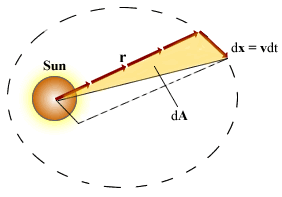
2.The radius vector drawn from the Sun to a planet sweeps out equal areas in equal time intervals.
3.The square of the orbital period of any planet is proportional to the cube of the semimajor axis of the elliptical orbit.

Half century later, Newton demonstrated that these laws are the consequence of a simple force that exists between any two masses. Newton's law of gravity, together with his development of the laws of motion, provides the basis for a full mathematical solution to the motion of planets and satellites. More important, Newton's law of gravity correctly describes the gravitational attractive force between any two masses.

Mathematical statements:
Kepler's second law
Where dA is the area swept by radius vector r in a time dt and Mp is the planet mass.
Kepler's third law
Where KS is a constant given by
MS is the Sun mass, G is universal gravitational constant and T is the time.

Law of Atmospheres and Boltzmann Law

The law of atmospheres, also known as the barometric law, states that the pressure n(y) as a function of height y varies as:

According to the ideal gas law, a gas of N particles in the thermal equilibrium obeys the relationship PV = NkBT. It is convenient to rewrite this equation in terms of the number of particles per unit volume of gas, nV = N/V. This quantity is important because it can vary from one point to another. In fact, our goal is to determine how nVchanges in our atmosphere. We can express the ideal gas law in terms of nV as P = nVkBT. Thus, if the number density nV is known, we can find the pressure and vice versa.
The pressure in the atmosphere decreases as the altitude increases because a given layer of air has to support the weight of the air above it — the greater the altitude, the less the weight of the air above that layer and the lower the pressure. 

Pressure and Altitude

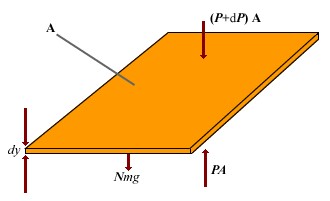
To determine the variation in pressure with altitude, consider an atmospheric layer of thickness dy and the cross-sectional area A.

Because the air is in static equilibrium, the upward force on the bottom of this layer, PA, must exceed the downward force on the top of the layer, (P + dP)A, by an amount equal to the weight of gas in this thin layer. If the mass of gas molecule in the layer is m, and the area a total of N molecules in the layer, then the weight of the layer is  w = mgN = mgnVAdy.

Thus A - (P + dP)A = mgnVAdy, Which reduces to dP = - mgnVdy
Because P = nVkBT, and T is assumed to remain constant, therefore dP = nVkBT dnV.
Substituting this into the above expression for dP and rearranging gives

Integrating this expression, we find
Boltzmann distribution law

Boltzmann distribution law is important in describing the statistical mechanics of a large number of particles.

It states that the probability of finding the particles in a particular energy state varies exponentially as the negative of the energy divided by kBT. All the particles would fall into the lowest energy level, except that the thermal energy kBT tends to excite the particles to higher energy levels.

Distribution of particles in space is
Where n0 is the number of particles where U = 0 This king of distribution applies to any energy the particles have, such as kinetic energy. In general, the relative number of particles having energy E is


Newton's Law of Cooling

Newton's Law of Cooling states that the rate of change of the temperature of an object is proportional to the difference between its own temperature and the ambient temperature.

Where  is the rate of change of temperature of an object with respect to time t.
 is the ambient temperature and K is the experimental constant 
From intial condition,   is obtained as follow

K can experimentally be found easily knowing that ,


Top